Author Archives: muzafferkal

shortreal system functions in System Verilog

SystemVerilog has two conversion functions related to the new shortreal type: $bitstoshortreal & $shortrealtobits.
Some simulators support shortreal but don’t implement these functions. I made some simple implementations as regular functions. You can find them here: https://github.com/muzafferkal/shortreal

Again this comes with no support. If you find them useful please send a short email. If you find/fix any issues, please send a longer email 🙂

-K

Open-source AXI3 Bus Functional Model (BFM)

This is something I have been thinking about for a while. Xilinx has a nice BFM for Zynq but it requires a license to run the AXI3 models. The following open-source AXI (3 for now) BFM is a start to run the Zynq BFM without any license. I have coded and tested enough of this models to verify that the default Zynq test program simulates and passes.
Here is the github project: https://github.com/muzafferkal/axi-bfm

Here is how I tested the models:

* Use Vivado 2015.2
* Create a new microprocessor project with Zynq and name it zynq_example.
* After your project is created, goto zynq_example\zynq_example.srcs\sim_1\imports\base_zynq_design directory and edit zynq_tb.v file which was automatically created.
* Add the following two lines somewhere in the module (this is necessary for Vivado to load the two sv files; otherwise they are not compiled and simulation doesn’t link)
axi3_master_bfm mstr();
axi3_slave_bfm slv();
* Add the two sv files to your project.
* Finally goto zynq_example\zynq_example.srcs\sources_1\ipshared\xilinx.com\processing_system7_bfm_v2_0\xxxxxxxx\hdl
and edit the following three files to rename the instantiation of the axi3_master_bfm and axi3_slave_bfm instances:

processing_system7_bfm_v2_0_axi_master.v
processing_system7_bfm_v2_0_afi_slave.v
processing_system7_bfm_v2_0_axi_slave.v

* At this point, you should be able to simulate the default design, observe that the led’s toggle and the simulation “passes”; Good luck and keep in touch.

Hidden Xilinx Vivado switches:

ERROR: [Synth 8-4556] size of variable … is too large to handle
set_param synth.elaboration.rodinMoreOptions “rt::set_parameter var_size_limit 4194304”
use the above switch to increase the variable size limit.

set_param synth.elaboration.rodinMoreOptions {rt::set_parameter dissolveMemorySizeLimit 147456}
this is for Synth 8-3391 Error.

set_param synth.elaboration.rodinMoreOptions “rt::set_parameter supportAsymRam true”
This is probably fixed. Asymmetric read/write width support.

set_param synth.elaboration.rodinMoreOptions “rt::set_parameter compatibilityMode true”

set_param synth.elaboration.rodinMoreOptions “rt::set_parameter controlSetsOptMaxFlops 10000”
setting controlSetsOptMaxFlops to 10000 will further allow optimizations on control sets into registers.

set_param synth.elaboration.rodinMoreOptions {rt::set_parameter simplifyCascadedMerge 0;rt::set_parameter mergeReconvergentCasePartitions false; rt::set_parameter mergeReconvergentLogicPartitions false}
Helps with how the Vivado Synthesis compiler is unrolling loops.

set_param synth.elaboration.rodinMoreOptions “rt::set_parameter reduceVariableBitSelect false; rt::set_parameter reinferPruneBitWidths false; rt::set_parameter constPropCarry false”

set_param synth.elaboration.rodinMoreOptions “rt::set_parameter forcePackBramAddrReg true”
the address register is not pulled into the block RAM if it has a feedback structure so this workaround is needed.

set_param synth.elaboration.rodinMoreOptions “rt::set_parameter doBramAddrRegResetTransform true”
This will pull reset from the address register so that it can be used to infer BRAM.

set_param synth.elaboration.rodinMoreOptions “rt::set_parameter constPropCarry false”
This problem is due to an optimization of constant logic during synthesis. Probably fixed in 2014.3
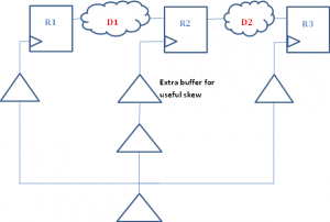
useful skew in Vivado

Vivado implementation tools are really getting close to their ASIC counterparts in terms of capability. The command phys_opt_design now implements useful skew insertion to meet timing. Useful skew is a technique where clock tree is manipulated to have non-zero skew for pipelines which are not completely balanced. Imagine 3 registers, R1, R2, R3 and 2 combinational blocks between them D1 and D2 between R1, R2 and R2, R3 respectively. Now if the delay of D1 block is longer than D2 and this causes timing failures, one has several options to remedy this situation. One can change the RTL and try to balance D1 and D2. This is the least desirable solution as it forces one to run all the regression tests again because RTL is modified. The second solution is to apply register retiming during implementation, ie let the physical optimization tool move some of the logic from D1 to D2 at mapped, maybe even placed gate level. This has a lower cost than RTL changes but it complicates formal verification efforts because now the RTL pipeline does not match gate level pipeline and formal verification needs to understand what retiming has been done. Also one has to verify that no sequential behavior has been changed.

useful-skew

The third and the lowest cost option is to add useful skew to the design. This is accomplished by increasing the time available to D1 block and reducing the time available to D2 block by adjusting the clock tree. Usually clock trees are designed for zero-skew ie all registers in a clock domain see a clock edge as close to each other as possible ie all leaf nodes of a clock tree to each register have the same delay from the root. This facilitates hold timing correctness and flops usually have a output delay larger than hold requirement so with zero-skew even a shift register with no delay between the two registers is guaranteed to have no hold violations with zero-skew. Useful skew changes this design paradigm. In our example because D1 is longer than D2, when it misses timing, there might be positive slack in the D2 path. In this case if we increase the skew to R2 register, this will make more time available to D1 path and less time available to D2 path. If D2 path has enough positive slack, this will allow both paths to meet timing. This method is the least costly as it is implemented in a post-place, post-route design by the tools and it doesn’t need any change in RTL or logic changes after synthesis and keeps the formal verification flow simple.

wonders of post route phys_opt_design -directive AggressiveExplore in Vivado

This option is extremely useful for post route optimizations for 7 Series designs. I recently had a design where route_design ended with 980 ps of negative setup slack and phys_opt_design -directive AggressiveExplore was able to reduce it to 69 ps of negative slack. At that point I moved one cell which was at the worst case path and another sequence of route_design -tns_cleanup + phys_opt_design -directive AggressiveExplore managed to push it to 15 ps of negative slack. At which point I stopped optimizing.

SystemVerilog interfaces don’t support hierarchy

I have been trying to design some AXI blocks with SystemVerilog and it seemed like to a good idea to use interface for this purpose

AXI has 5 channels: read and write address, write data, read data and response channels. Of these read and write address channels are identical and other channels have minor differences from each other. As someone with a decent programming background (in addition to strong logic design), it was pretty obvious that one could design an address channel interface and embed two of these in an AXI interface. The other interfaces could be managed with, say, inheritance or embedding (i.e. “ISA” or “HASA”) to account for the differences. Alas it was not meant to be. Interface don’t support sub-interfaces nor inheritance which restricts their use to very simple cases. This is such a shame. I am not even going to wish that it be fixed in the next version of the standard. By the time these get addressed in 1800 and are implemented by the EDA vendors, I am hoping that I’ll have moved to strictly C based logic design.

Kintex-8 and Virtex-8 ???

It seems Xilinx has already released some tools for Kintex-8 and Virtex-8. Maybe even chips are in the wild. I wonder if they are 20nm parts. It would be so nice to get an eval board if they do exist. One reference to Virtex-8 is here: http://www.xilinx.com/innovation/research-labs/keynotes/RAW2012_keynote.pdf

Here is a report from Digitimes which says 8 series parts will be manufactured on TSMC 20nm process: http://www.digitimes.com/news/a20121115PB200.html

Incremental Place & Route with Xilinx Vivado toolset

I’ve been working on a design which is implemented on a Xilinx Series 7 FPGA. I had a -50ps timing violation and it seemed that the placement of the cells in the critical path could have been done better. In an ASIC flow this would be quite easy to fix but previous generation of Xilinx tools didn’t support this functionality easily. The current Vivado toolset is significantly better. It turns out after a design placed & routed, it is possible to move cells with “unplace_cells, place_cells” commands and run route_design again which in turn repairs all the generated DRCs and generates another valid implementation. Kudos to Xilinx for delivering a good set of tools worthy of the Series 7 FPGAs.
BTW the final timing result is -8ps which is good enough for this prototype; although fixing it would not have been difficult if needed.

Initial impressions of Vivado family toolset from Xilinx


I have been using Vivado toolset for a month now, on & off as I have current designs on Spartan 6 and Virtex 5 which need RTL improvement so ISE is still in use but I find myself wanting to go back to the Kintex project so that I can use the Vivado back-end tools more and more. I am also working on a Zynq system which will replace the existing hardware so future looks nice.
In terms of Vivado back-end, the timing system is a big relief from UCF. Full SDC constraints are supported with an embedded TCL interpreter. So far I have seen one bug where the timing optimizer sometimes hangs while fixing holds but it is rare and I have heard from Xilinx that they know about it and have a plan to fix.
Vivado simulator luckily is not specific to series 7 chips and its UI is slightly better than ISE simulator. One welcome addition is the ability to view buses as analog waveforms which is nice.
Last but not least Vivado HLS is quite interesting too. So far I have written a small amount of fixed-point C++ code and translated it to RTL but not compared to QOR to my existing hand-written RTL but it’s nice to know that there is an option.
Overall Vivado family is evolving nicely and I am pretty happy with the current performance.